By Thomas A. Little
Methods for Design-Space Generation
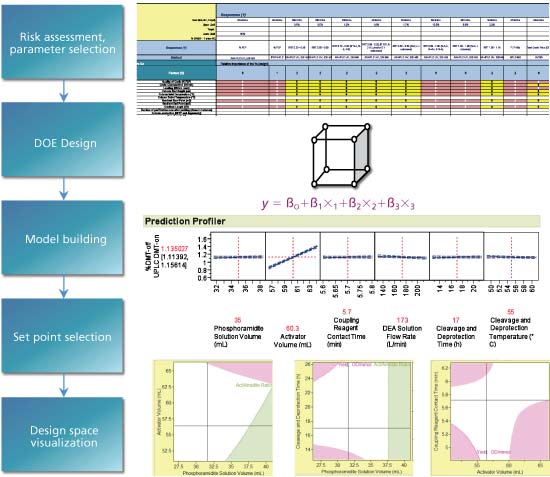
Design-space generation always begins with CQAs, risk assessments, definition of materials, process sequence, scale, and equipment (see Figure 2). Experiments are designed that meet the development objectives and goals. Studies are converted from raw data into product, material, and process models that explore the parameters/attributes that were identified in the risk assessment. Thoughtfully constructed designed experiments or other representative data sets may be used in equation/model generation and design-space generation.
Phase-appropriate design-space generation
The design space should be defined by the end of Phase II development. Preliminary understanding of the design space may occur at any time; however, it must be defined prior to Stage I validation (2). Waiting to develop the design space until Phase II assures the specification limits and process definitions are stable and well defined prior to design-space generation and evaluation.
Common Misconceptions in Defining a Design Space
Misconception One: Design of experiments is the same as design space
Design of experiments (DOE) is not the only method for determining a design space. Other methods can be used including known scientific equations and regression techniques. DOE is generally the most common approach. DOE helps to generate the equation prior to design-space determination but it is only one step in the process.
Misconception Two: Only critical parameters should be in a design space
Design space can include all parameters affecting product quality. Design space can include parameters that were held constant.
Misconception Three: Edge-of-failure is needed for a design space
Failure mode experiments provide useful information, but are not required.
Misconception Four: Safe operating region
Another common misconception is that all of the area within the extrapolated design space is considered a safe operating region. Extrapolations into uncharacterized regions within the design space add risk.Design space is a mean (average) response surface model and does not assure all samples will meet all batch acceptance criteria. Simulation is typically used to determine Cpks and failure rates.
Steps in Design-Space Generation
The following steps should be taken in design space generation.
Determine the business case and CQAs
Make sure you know why the experiment is needed and what knowledge deficit it will fill. Make sure you know why this experiment is needed or not needed when rationalization of developmental areas.
Single-unit and multiple-unit operation approach
Design space can be generated for each unit operation and/or it can be generated across multiple unit operations. Generally across multiple-unit operations, experiments are more representative of the entire process the drug product or substance will experience.
Risk assessments
Risk assessments are used to rationalize the selection of parameters. They can be organized as a factor/response type risk assessment relative to CQAs or they can be organized as a failure mode effects analysis (FMEA) type approach relative to CQAs. Either way, a clear line of sight between CQAs and the process parameter and material potential impact aid in parameter selection (4).
DOE design and scale considerations in the DOE
DOE generation needs to be linked to the risk assessments and business objectives. Full-factorial or D-Optimal custom designs are most common depending on the problem complexity. Make sure to include factors that may affect the process at scale if the experiments are run at small scale.
Data analysis and transfer function generation
A multivariate analysis software application needs to be used to analyze the data, eliminate any outliers, determine statistically significant factors, quantitate the effect size of each factor, and generate the model (equation). Critical process parameters (CPPs) and critical material attributes (CMAs) can be defined based on effect size.
Set point selection and robust optimization within the design space
Once the model has been generated, optimization of all set points to find the most robust (stable) area within the design space is defined.
Visualization of the design space at set point
Profilers, interaction profilers, contour plots, and 3D-surface plots are used to visualize the design space. Specification limits and all acceptance criteria must be defined to determine the edges of the design space.
Determine X parameter
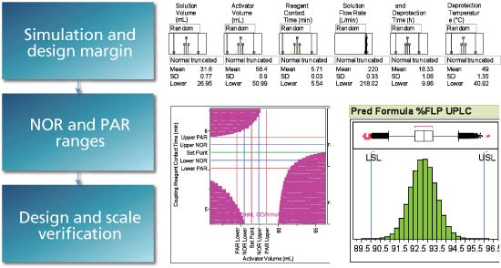
Determine the variation of each X parameter at the set point (one standard deviation) and make sure the method variation is known (one standard deviation intermediate precision). The goal of simulation is to model 100% of the variation in the process. This includes the variation from the model (RSquare) plus the variation due to other factors and the variation from the analytical method. Variation due to stability may also be included as a noise factor.
Simulation, determination, and visualization of design margin
Using all sources of variation, simulation is used to determine the failure rates at set point. K-sigma limits are used to open up the variation at set point and then determine failure rates. Cpks of 1.33 or higher are generally considered good design margin (PPM of 63 batch failures per million batches or less). Random error is added to the model to make sure all sources of error are included.
Determine normal operating ranges and proven acceptable ranges
Finalize the design space by determining the normal operating ranges (NOR) and proven acceptable ranges (PAR). NORs are typically three sigma design windows, and PARs are typically six sigma design windows around the set point.
Small-scale and at-scale design space verification
Verification runs at both small scale and at scale are used to verify the model. Comparing values from the verification runs to the model help to assure the model has reasonable predictive power. Verification runs for small-scale and at-scale processing conditions are essential for model verification. Rescaling the model for the full-scale run conditions may need to be done.
Product and process control applications
Based on the equations, selection of the control strategy can take place. Process controls can be one of the following: feed-forward, feedback, in-situ, XY control or XX control, in process testing, and/or release specification testing and limits. Design space helps to determine control parameters based on parameter influence and sensitivity. Also, the transfer functions used in design space generation are used to calculate adjustment amounts when adjusting back to target.
Validation implications
Stage I validation requires a discussion of process knowledge and suggests the demonstration of a design space (2).
Submission implications
How the design space is used will modify how the submission will be generated and communicated. If it is used to show process knowledge, that is one kind of submission. If it is a basis for control with adjustments, that will follow another type of submission and is more complicated (see Figure 3).

Conclusion
Modern ICH standards encourage design space generation in new product development. Use of design space increases product and process knowledge and reduces risk. Using a risk-based and multivariate approach is a best practice in generating the design space. Use of design space is best when establishing set points, tolerances, and PAR ranges. Best practices include determination of failure rates and design margin during development as well as using the transfer functions from the design space for process control. Intended design space and use should be clearly communicated to regulators. FDA generally welcomes discussion on design space with applicants so be sure to discuss the design space and submission logic with FDA working groups as needed.
References
1. ICH, Q8(R2) Pharmaceutical Development (2009).
2. FDA, Guidance for Industry, Process Validation: General Principles
and Practices (2011).
3. S. Chatterjee, “Design Space Considerations,” FDA, AAPS Annual Meeting, October 14, 2012, Chicago, ONDQA/CDER/FDA.
4. ICH, Q9 Quality Risk Management (2006).
About the author
Thomas A. Little, PhD, is president of Thomas A. Little Consulting, drlittle@dr-tom.com.


